Thursday, 30 June 2016

Residual Current Circuit Breaker (RCCB) : How It's Works


RCCB (Residual Current Circuit Breaker) are the most important device that protect your home from getting over current by fault current. RCCB comes with two types, one are single phase with 2 pole and another are three phase with 4 pole. Even it's different,but the principle of operation are the same. 


The picture below shown is the inside view of RCCB. It's look like complex,but is not. To understand the working principle,let's look at the schematic of RCCB.
There's are several component are working together,to protect your home. The supply is give by single phase or three phase. Then, it's flows through a round shape with turns of coils around the core. In single phase, only live coil and neutral coils are there. If three phase, each phase has own coils. When the coil energize, it's produce an electromagnetic field. The electromagnetic field produce by how much current are induce. When the coil energize in normal condition, both phase coil and neutral coil are balance. It's means your home wiring are in safe condition. If between the coil is imbalance,there's a sensing coil will detect the imbalance current and stop immediately.

In general, RCCB trip in 200ms. A healthy RCCB will trip 40ms. The break time is depends on the current rating on the RCCB. In home RCCB,the current rating is 30mA. If the current is higher than the 30mA,the RCCB will trip.

To make sure ,your RCCB works properly,there's is two test to make sure it's work perfect.

1) Push Button Test 

Every RCCB production,there's a push button to test for make sure,the device is work properly. When you press the test push button,current from live will connect with neutral means it will short circuit and trip by itself  with the help of sensing coil and relay. 

2) RCCB Tester

RCCB Tester are use to calculate the speed of the break point when earth fault or over current occur. There's a build in plug that plug in on socket.


There's three range the tester going to determine the speed of the RCCB break point. THe first range is the current rating.Choose the suitable current rate on the range.The second range is the trip selector. On selector, No Trip,Trip and Fast trip. Each range will determine the speed of the RCCB break point.The last range is the angle. 0° angle is the staring point for sne wave of single phase and 180° angle for running point. This will make a difference of break point on each angle.

RCCB must be in good condition. It's like a bodyguard for your house wiring. Check twice a month and keep your bodyguard safe I mean the RCCB :)

Tuesday, 28 June 2016

Types of wiring : Cable Tray wiring.

When enter a office or data center maintenance, you will see a large amount of power cables and fiber optic cables are hang over the room ceiling. This cables are supported by a long steel tray called 'Cable Tray'

Cable tray wiring are used to transmit and receive power or data from one place to another place. If a office room wants to send data and also want power supply for each computers in it,concealed or surface wiring are no recommended,because this will cost more. So cable tray are used to solve this problem. There's many types of cable tray wiring,but the function are the same. It's not a big deal for this wiring.It's easy to understand how it's works.

 1) Over head Cable Tray Wiring

2) Wall mount Cable Tray wiring

Another function of cable tray are, heavy duty cables or armoured cables like SWA (steel wire Armoured) cable can hold on cable tray to distribute power from low or high voltage switch board. Cable tray can come from various type of size and colors like Grey,Orange,black and so on.In wall mount cable tray wiring,the cable tray is hold by a 'U' shaped and 'L' shaped bracket.

The brackets are attach with screw and nuts to give extra support and grip.
 

There's some advantage and disadvantage for cable tray wiring

Advantage :
  1. Easy installation
  2. Adding or changing wiring can be done easily
  3. Can upgrade and modified wiring
  4. Can be done damaged by weather or heat.
  5. Easily detect problems in wiring
Disadvantage :

  1. Skilled worker needed
  2. Dust easily ruins the wires
  3. Need extra support like bracket
  4. No mechanical and chemical protection
  5. No space between cables when large amount of cables on cable tray         

Monday, 27 June 2016

Electromagnetism : DC Motor

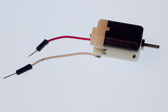
In your childhood,you probably seen this small machine runs your toys and remote control cars. When the battery run out,this machine stops run and you open the toy and see this small machine and you repair it like a mechanic!! This small cute machine called 'DC Motor' or a 'Conduction Motor'

DC(Direct Current ) motor runs in direct current like from batteries. This DC Motor have many parts. Armature,Permanent magnet,commutator,carbon brush and coils or winding.
Function of DC Motor parts :

1) Stator magnet 
 
   =Produce magnetic field

2) Winding         
=The winding made of copper wind around the armature slot. The winding produce a magnetic filed when the current flows through the copper winding.This produce opposite magnetic field and cut the magnetic flux and rotates the armature.

3) Armature :
   =The armature is the rotating part of the motor and wind a copper conductor along the armature slot.

4)Commutator :
   =Supply DC current by commutator to armature winding.

5) Carbon brush :
=Distribute DC supply and send to the carbon brush.the carbon brush emit a small amount  if spark on the commutator by friction.that shows the carbon brush distribute power for every rotation per second.

Working principle of DC Motor :


In the picture above shown,a DC power supply given to the carbon brush.This carbon brush will distribute power to the commutator.The DC current flows through the armature winding. this winding will produce magnetic field around the armature. this armature winding produce opposite magnetic poles. This will produce torque or force. In the permanent magnet,there's north pole and south poles. between the poles there's magnetic line as the picture shown in green color line. 

When the current pass through the conductor,it produce the opposite magnetic field that rotates the motor. The permanent magnet poles are N-S and the conductor magnetic field poles S-N. In normal magnet,Similar pole repel and different pole attract.The same thing goes on here. The similar pole repel and move the other side of the pole and attract then repel again.When the north pole attract the south pole from armature winding,the motor won't rotate and stop at 180° rotation. To avoid happen this,commutator will flip the armature for each rotation and rotate to 360° by move freely.

 Now the motor rotate in forward. So to make the motor rotate backward, the polarity (terminal of DC Motor) Change to - (negative) to + (positive). So the motor will rotate in backward. When the motor rotate backward, the armature winding produce magnetic field like north pole to south pole. so this will attract the opposite pole and produce torque.

To determine the rotation of the rotor Fleming's left hand rule and right and grip rule are used. The Fleming's left hand rule will determine the the rotation of the motor while the right hand grip rule will determine the direction of the magnetic field.

 
 Right hand grip rule

Fleming's left hand rule
 
Now you know the secrets behind your toys. Try open your toys and dismantle the DC motor. You will easily understand the parts of it. It's simple and easy

Sunday, 26 June 2016

Electrical Conduit accessories

Conduit are widely used in workshop and heavy duty industrial areas. Conduit also can used in residential areas,but certain place are no recommended. Conduit accessories help the wiring to be protected from mechanical and chemical damaged. Conduit accessories comes with variety of size and shape,but we only look about the basic one. Lets look about electrical conduit accessories.  
 
 
1.End box

Every light in your house wiring have end box.This end box will mount baten light on it. So it can stay properly.

2.Two way junction box


Two way junction box used in between two PVC pipe.This allows install wires in two direction


3.Three way junction box


This three way junction box has three way that wires can insert through three direction. 

4.Four way junction box


 This four way junction box can install wires in four direction.

5.Elbow and Long bend


Elbow and long bend are shape in 90° that can easily shape without using conduit bender.


 6.Coupler


In conduit wiring coupler are used to join two conduit pipe by make a thread end of the pipe. Another coupler provide external screw that can join socket or switch metal clad box.

7.Saddles and Bar
 
 Saddles and bar used to hang the conduit pipe on the wall.

8.Metal clad box
 This metal clad are used to place any switch and sockets depends on size. The metal clad box provide with ground connection that protect wiring from getting fault.

9.Metal Distribution Board

 This metal distribution board used in workshop and industrial areas for give good mechanical and chemical protection

Friday, 24 June 2016

Electrical Test : Insulation resistance test

Insulation resistance test are so important test in electrical wiring.If your house wiring cable are safe and no wounded,the cable will won't interference to other cable.If the cable is wounded,there's high chance short circuit or earth fault happen To make sure your house wiring are safe,insulation resistance test will determine it by doing this test.

The picture above shown is the meter used to test insulation resistance for your house wiring. This meter called Meggar Meter. This meter works similar to Multimeter. You can se this meter to test polarity and continuity test and the range are provided with 250-1000 AC V and 20Ω-2000Ω. Modern megger meter have test button,but old classic meggar meter have pedal to spin to produce AC current for send current flow through the wire to test. In good condition, the meggar ohm will show infinite in the meter. It's means your house wire are in good condition.

We now know the tools,but we don't know how to use this meter for test. Let's look about it.In insulation resistance test, there's two probe. One is Live and another is Earth or Ground.  So one probe point at the first terminal and earth probe are point at other terminal. So the probe pointing the terminal are like this for

Single Phase :
N-L
E-L  
N-E

Three Phase :

R-Y
Y-B
B-R
E-B
E-Y
E-R
N-R
N-Y
N-B
N-E   

Let's look some example how to use this meggar meter.

This picture above shown is insulation resistance test are check in three phase distribution board that Live probe are point at Red phase and earth probe point at Neutral.

This picture above shown is insulation test are check on light bulb. Ih this test, live probe are point at Live terminal and ground probe are point at earth.


This picture shown is insulation test are check in 13A socket. In this test live probe are point at earth and ground probe are point at neutral.