Thursday, 8 September 2016

Calculation of Kirchhoff Voltage law

In previous post we look about theory of kirchhoff voltage and current law. Now we going to learn how to calculate kirchhoff voltage with example of a circuit diagram. It's easy to understand and you need to think clearly to do calculation on the circuit.

KIRCHHOFF VOLTAGE LAW : The sum of the voltage drops around any closed loop is zero.

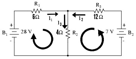
Based on the circuit diagram below we going to calculate the value of voltage and current.


Now on the circuit diagram you will notice that there's no value of voltage and current on each resistor. Only value of resistance is present. In order to calculate the value of voltage and current we need to split this circuit into two loop.


 Now we going to use Kirchhoff current law to determine the node for that circuit so:

1) I1+ I2-I3 = 0 
2) I1+I2= I3
Therefore for kirchhoff voltage law :
                                    
                                 Loop 1 : VR1+VR2-VS= 0
                                               VR1+VR2=VS  
                                 
                                 Loop 2 : VR3+VR2-VS =0
                                               VR3 + VR2 = VS
To find current for each resistor we need to use ohms law to determined the value of current for each resistor. So the equation will be :

V= IXR

For Loop 1 : [I1X6Ω]+ [I3X4Ω] = 28V 
                     I1 =28V/6
                         =4.7A
                     
                     I3 = 28V\4
                         = 7A 

For Loop 2 : [I2X12Ω] = 7V
                    I2 = 7V\12
                        = 0.58A
                    
                    I3 = 7V/4
                        = 1.75A

Now we get all the value of current, so it's easy to calculate the value of voltage each resistor.  

VR1 = 4.7A X 6Ω = 28.2V
VR2 = 7A X 4Ω = 28V
VR3 = 0.58A X 12Ω = 6.96V
VR2 = 1.75A X 4Ω = 7V loop 2    

Now we get all the value of voltage of each resistor. Now we going to total all the voltage,current and resistor. To calculate the total value of voltage,current and resistor, we need to calculate separately. So teach loop will be in series circuit and you need to apply series circuit formula.
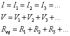

 
Voltage Loop 1 : V= VR1+VR2= [28.2V+28V=56.2V]
Resistance loop 1 : R= R1+R3= [ 6Ω+4Ω=10Ω]
Total Current loop 1 : I=V/R =[56.2V/10=5.62A] 
The total voltage in loop 1 is 29.95V this is because, the current is drop in R1 and increase in R2.

Voltage Loop 2 :  V= VR3+VR2= [6.96V+7V=13.96V]
Total Resistance loop 2 : R= R2+R3= [ 4Ω+12Ω=16Ω] 
Total Current loop 2 :  I=V/R =[13.96/16=0.87A] 
The total voltage in loop 2 is 13.96V this is because, the current is drop in R3 and decrease and increase in R2.

WELL LEARN HOW TO CALCULATE KIRCHHOFF VOLTAGE LAW WITH OHMS LAW. IN NEXT POST WE GOING TO LEARN CALCULATION OF KIRCHHOFF CURRENT LAW.TILL THEN KEEP TRY AND MASTER THE LAW OF ELECTRICITY.


Wednesday, 7 September 2016

Bus Bar

Bus is use for transport people to one place to another. Bar is a long connected metal or non metallic shaped support something. When you connect Bus and Bar. it meaning will be is a long bar like conductor that transport current one place to another. Nice understanding right. So we going to look a bit deep about Bus Bar.


Bus bar comes with various types. Here the picture below shown the types of bus bar. These bus bar is made of copper or aluminum with variety of angles according to send current to one place to another.


 Not only bus bar comes with variety of types,but there's also we need to know where we use the bus bar for. Lets look at some pictures where the bus bar use.


1) Bus Bar in Distribution Board
This bus bar is made of aluminum and copper with 240V/415V. this bus bar connect all neutral and earth wires separately.

2) Bus Bar in MCB (Miniature Circuit Breaker)

Instead using wires to connected so many MCB in distribution board,this bus bar is used to connect as much of MCB incoming of MCB. This will distribute current to all MCB without connecting wires to each other.


3) Bus Bar in Three phase wall mounted distribution

This bus bar is used for three phase distribution in factory, workshop and heavy duty areas. This bus bar is wall mounted and easily connect and disconnect.

4) Bus Bar in Main Switch Board,Transformer and high voltage distribution system
 This bus bar conduct high voltage that will connect with transformer,main switch board and high voltage distribute system to send high voltage to nearest switch gears or substation.

Bus Bar Insulation

leaving bus bar without insulation while there's current in it is absolutely dangerous. This wil harm human and animals that accidentally contact with uninsulate bus bar. So insulation like bus bar rubber insulator or paint the bus bar with thick insulating paint.

1) Rubber insulator 

Paint Insulation  

How Bus Bar is Connect 

Bus bar has it's own slot with nuts and bolts to connect cable with tightly. Cable is crimp with cable lug and slot in nut and screw with bolt. If the didn't bolt tightly, the terminal of bus bar will get heated or sparking.
Untight bolt result of burning bus bar and weaken it.


TODAY YOU LEARN SOMETHING NEW IN YOUR LIFE. WANT TO KNOW ABOUT MORE ON ELECTRICAL TECHNOLOGY COMMENT OR EMAIL ME ABOUT ELECTRICAL  TOPICS.

Tuesday, 6 September 2016

How to make end cap for trunking

We previously learn about how to make tee junction,90 and 45 angle. The last final one for this trunking is making end box. To do end box fro trunking is easy and simple to master the skill to do. You can make end box to any size of trunking anyway as the 90 or 45 and tee junction do also. So let make end box for trunking.
   
Tools needed :

Metal cutter
Ruler or Measuring tape
Pencil (for draw lines on trunking)


WARNING : 
BE CAREFUL WHEN YOU CUT TRUNKING,THIS MAY CAUSE INJURIES FROM SHARP EDGES BY CUTTING THE TRUNKING. WEAR GLOVES TO AVOID INJURIES.

1) prepare tools and trunking to get started.

2) Now measure the end of trunking in 50mm.

3) Make a line at left,right and middle of trunking after measure in 50MM.

4) Cut the sharp edges by guided red circle and make it short,because it can easily move in the trunking.

5) Now slot the end part inside the trunking
   
6) Finally you done a perfect end cap for trunking 

YOU CAN MAKE THIS END BOX FOR TRUNKING IN ANY ANGLES. THIS END BOX IS TO END THE WIRING TO ONE PLACE OR TO MAKE ADDITIONAL END CIRCUIT LIKE SOCKETS AND LIGHTS. 

Monday, 5 September 2016

Feeder Pillar

Every time you see at road you will notice this huge electrical panel always stay forever at road. This panel is important to all street light in your country. Do you remember about underground cables that we learn in previous post? yes!! the post introduce a panel called 'Feeder Pillar' and we going to learn about it.

Feeder Pillar is a huge electrical panel specially for street light. This feeder pillar power up so many street light in highway roads, apartment with street light and so on. So what's inside feeder pillar.


This feeder pillar made of steel equip with water proof. Inside feeder pillar, there's fuse. This fuse has 63A amperage. Each fuse is connected to bus bar in three phase.The out going of fuse is connected to street light. before bus bar, there's circuit breaker or Moduled Case Circuit Breaker (MCCB) with 100A amperage. In some feeder pillar have Zero Current Transformer (ZCT) to provide additional protection to busbar. Additionally, voltmeter and ammeter is install in that feeder pillar. In modern technology, some feeder pillar install radio communication to verify this feeder pillar work correctly and efficient.


A  63A amperage fuse can connect more than 100 light in each phase in three phase. The incoming for fuse is connect to the bus bar. the outgoing for fuse is connected to street light. the street light fix with SWA or XLPE underground cable and burry underground to make it safe. All street light are connect in parallel so if on light goes off another still work. the street light produce 320-1000 watts that can damaged human eye so it's install high enough to make the road bright and easy to see.

Sunday, 4 September 2016

Electromagnetism : How Speakers Work


Afrojack,Martin Garrix, and Bassjackers they all make their music louder even louder in concert. This louder music comes from a evolutionary sound making device called speakers. Every where you go, there's always speakers making noise. Nowdays headset,portable speakers are carried by people. So how speakers make music louder!!!! Lets find out.

Speakers comes with variety of sizes and shapes. This speakers works by vibrating the cone by electromagnetism. This vibration makes sound wave to let us to hear. Lets see the components of speakers that makes you understand clearly.
As you see the cross section of speakers, there's a permanent magnet and the coil. This is the main part of the speaker. The permanent magnet makes a magnetic field. When the coil is energize by incoming electrical signal,this coil also makes its own temporary magnetic field. When this happen, the coil move inward and outward by changing the magnetic field by the coil. While the coil moves, the cone also move and vibrate into sound. 


Even the speaker make sound and enough to hear, these speaker is connect to amplifier. This amplifier turn weak audio signal into high audio signal that enable us to hear. Every speakers are made from this concept till now from the speakers in your house and to the headset speaker in your ear.  

OHMS AND POWER OF SPEAKERS


Every speaker you see,there's rate of resistance (Ω) and power (W). The wattage of speaker is for example, your speaker has 12W, so your speaker can handle that much of power. In resistance of speaker, the lower the rate of ohm,the lower the resistance. If less resistance of speaker and you plug 12W 2Ω speaker,this will give more power to speaker,but this will damaged your speaker.

If your plug 12W 8Ω speaker,means high resistance, your speaker will not damaged by resist certain amount current and allow right amount of power to your speaker. If you choose the right amplifier and right speaker, the both will be last long forever.

NEXT TIME YOU TURN THE VOLUME UP,ALWAYS REMEMBER YOUR SPEAKER IS VIBRATING TO MAKE YOU HAPPY  

Thursday, 1 September 2016

How to draw three phase electrical floor plan.


In previous post about floor plan, we learn about how to draw single phase electrical floor plan. Very easy and simple right. Now we going to learn the same thing but further a bit and this is the last one for electrical floor plan. So don't miss it and lets get started.

To draw three phase floor plan you need to think how to distribute three phase into single phase for each electrical accessories. Another thing for this floor plan  you no need to draw wiring on it. you just need to label three phase terminal like R,Y,B or R,S,T. We going to use the similar floor plan as we done in previous post.


There's 12 electrical accessories in this floor plan. To distribute three phase terminal to those electrical accessories you need to think carefully before you label it. In my point of view Im going to distribute electrical accessories according to three phase terminal

R : 4 Down light and ceiling fan a socket.
Y : 1 Fluorescent light and socket
B : 1 Glob light and a  2 socket.

Now we have the right distribution of three phase system in this floor plan so now we can label in this floor plan. Now we going to label the red phase of three phase. 

1) Red phase label : 
We finish label the red phase. But the difference in this phase is there's R1 and R2. This is because you wired light and ceiling fan differently than socket. Light and fan need 6A MCB and sockets need MCB 16A,20A or 32A. so you need to wire individually.  


2) Yellow phase label :  
We done the same thing as we wire the red phase. fluorescent light is label Y1 and sockets go Y2.

3) Blue phase label :
Now lets label the blue phase. 

Now you complete your three phase electrical floor plan. the reason why we didn't draw wiring on it, because is too many electrical in three phase may hard to draw wiring and it can be more lines to determine where the wire connect in the floor plan.