Sunday, 23 October 2016

Electromagnetism : Squirrel Cage Rotor Vs Wound Rotor


In previous post, we learn how induction motors works and their parts also.Hope you dummies will understand the working principle too. Now going to learn something about the motor parts. Not too many but only one parts that is rotor (The rotating part of the motor). So what so special about rotors. Right now dummies let look some theory about rotors.

Unlike motor's stator has many windings,but in rotor has two type of rotor. One is Squirrel cage rotor and another is Wounded rotor. The both rotors has common and differences. SO let compare them and choose which rotor is the best.

The common in this both rotors are it create magnetic field and allign stator magnetic field to rotate. 

1. Squirrel Cage Rotor

Squirrel cage rotor are commonly used in induction motor. The construction of this rotor are simple to understand. This rotor has conductor bar made of copper or aluminum. The conductor bar are short circuit by placing end rings. Steel lamination are place in the rotor with conductor bar. The reason why steel lamination are provide efficiency and prevent heating up.

2.Wound Rotor 
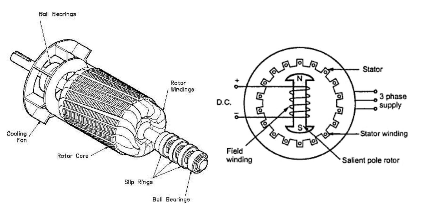

Wound rotor has same construction like squirrel cage,but little different. This rotor has rotor winding and slip rings. It also laminated core to provide efficiency and prevent heating. This rotor also used in induction motor and this motor also know as synchronous motor. The rotor get supply by DC power source.

Which one is best ? Squirrel cage rotor or Wound rotor?

To determine which one is the best, Well you need to know the difference.These rotors play important role in to turn electrical energy into mechanical energy. The picture below shown is the difference between these rotor and dummies you will determine which one is better
 
IN MY OPINION, SQUIRREL CAGE ROTOR IS THE BETTER,BECAUSE HAS HIGH EFFICIENCY AND LESS MAINTENANCE. SO WHAT'S YOUR THOUGHT LEAVE A COMMENT AND STAY ELECTRIFY


Friday, 21 October 2016

Why wires are used according to the current rates

Wires are so important to electricity. Without wires you can't imagine how the world will be. We have different size of wire and these wires are installed according to the current rating. So why do wires installed in that way? Well dummies you really need to know why!! you are in right place ton know it. Lets get start.
In wires two good electrical conductors are used. We know the popular one in electricity world is copper. Another cheap and lightweight electrical conductor is Aluminum. So these conductors comes with different size,diameter,length but these factors are only determine by the resistance of electrical conductor. 

Not all electrical conductors are pure. It has some resistance too. Even the best electrical conductor silver has resistance 1.59. x10-8.So Copper has 1.68 x10⁻⁸ The resistance value cause the voltage drop if the wire length increase. From the resistance of copper, the length,size,core of the wire is determined. There's a list to identify the current capacity,voltage drop according to the size of wire.
The voltage drop is effect the wire,but it effect the efficiency like energy loss in form of heat. So the right current is choose in right size to flow the current in the conductor. So the it won't effect the efficiency of the wire and the energy loss can be reduce.

In house or industrial wiring, the voltage drop is care about much because the wire length isn't long so the voltage drop may occur in small amount. So dummies if you want to do a house or industrial wiring, make sure you choose right size of wire.

ELECTRIFYING FACT OF THE DAY :
YOU CAN USE ANY COLOR OF WIRE IN ORDER TO LOWER THE COST,
BUT IT'S AGAINST THE RULES OF ELECTRICAL ORGANIZATIONS DEPENDS
ON COUNTRY.    

Wednesday, 19 October 2016

Neutral and Earth are friends

Wires are amazing!!! Because that are the nerves for electricity to power your home's light bulb. In Single Phase there's Live,Neutral and Earth,Further more there's Red,Yellow,Blue,Neutral and Earth in three phase. But there's similarity in the wires especially in neutral and earth. So what are the similarities? We going to find out!!! 

If you want to know the similarities between neutral and earth, we should know the difference. Live wire is a current carrying conductor so it has potential also know as voltage. Neutral wire is carry current back to the source to make one complete loop. Earth wire is a protective wire that has zero potential means there's no current. Even you touch the earth wire, you won't feel get shock but don't try this at home.
The picture above shown is a 13A socket. From this picture we can know the socket receive the same current and goes back to the neutral and complete one loop. So this same current goes to the socket and back to the socket are same. This is called Balanced Current. This situation is normal for a single wired socket.What if the socket connect with two or more socket?
The picture above shown is 2 sockets connected in parallel. In parallel circuit the voltage will be the same but not the current. So the live carries 32A and goes back to neutral with 26A. Although it's complete one loop but this circuit carries Imbalance Current. This imbalance current need to dissipate. When comes to dissipate current the earth or grouding system kicks in to do this job.


In home and industrial distribution board, earth and neutral are connected isolatedly. but in serivce line (A.K.A Overhead Transmission Line) has ground wire or earth wire.These wire will dissipate the imbalance current in ground. In some cases this imbalance current will brought back to the substation and grounded there. So this will complete the circuit.

 The reason why neutral and earth are connected isolatedly because the earth conductor acts as protection to your electrical appliance by the help of RCCB. The RCCB will detect any earth leakage and immediately shut down the electrical supply. The leakage current will dissipate by earth copper tube.


 NEXT TIME WHEN THE RCCB TRIP AND SHUT THE ELECTRICAL SUPPLY TO YOUR HOUSE,ALWAYS THANKS TO THE EARTHING SYSTEM THAT ALWAYS READY TO PREVENT YOU FROM GETTING ROAST. I MEAN GET SHOCKED :p


Tuesday, 18 October 2016

Installation of International TV broadcast system

In previous post, we learn how to install TV antenna. Now we going to go further in to install  TV international broadcast system. There's more things you need to know before we learn about this so dummies pack up your tools and let start to do some handyman stuff. lets get start.

WARNING : 
THIS POST ONLY FOR LEARNING PURPOSE. ACTUAL INTERNATIONAL TV BROADCAST SYSTEM ONLY INSTALL BY WORKERS FROM SATELLITE TELEVISION PROVIDER COMPANY. SO DON'T TRY THIS AT HOME. CALL YOUR SATELLITE TV PROVIDER TO INSTALL IT. 

Let say you want to install SkyBox in your home. So workers from SkyBox company that will be your Satellite TV provider. The workers will install the parabolic antenna first. The install this antenna with bracket and turn the antenna in right direction in order to get good signal. 

When the signals from different frequency hit the parabolic antenna, the signal will focus in one point and then catch by feedhorn. These signal will convert into Audio Video form,in other words watching TV. This antenna made in curve shape in purpose to reflect signals in one focus point. the feedhorn is wired with coaxial cable to the decoder.
Now lets move on to the decoder. The decoder will provide by the SkyBox company. But you need to pay first to the provider. The coaxial cable from feedhorn will wired to the outlet at the decoder. From the decoder there's several outlet to the TV like AVI,Components,VGA,and HDMI.
Now the workers will plug in the outlet to TV for display. Don't worry dummies for distort display,because there's already built in power supply,signal booster and so on. After plug in cables, the workers will program some settings in the menu and the work is done. Now you able to watch Game Of Thrones in SkyBox.

 ELECTRIFYING FACT OF THE DAY :
THE REASON INTERNATIONAL BROADCAST CHANNEL ALWAYS DISTORT OR UNAVAILABLE DUE TO RAIN BECAUSE THE CHARGE PARTICLES INTERFERE WITH THE MICROWAVE THAT TRANSMIT AND RECEIVE SIGNAL FROM THE SATELLITE IN SPACE TO YOUR HOME.

Monday, 17 October 2016

Joule's first law (Joule Heating)

From your light house bulb to your electric kettle works by electricity.But one thing to be sure, every electrical appliance create heat.maybe some don't create heat but most do. So why heat create in electrical appliance and what's common in joule's first law. Alright dummies!! we going to find out.

Joule's First Law (A.K.A Joule-Lenz Law) : State that power heating generated by electrical conductor to the product is proportional to the current.

Heat generate most of electrical appliance. In terms of electrical, heat consider as a power loss. Because when the more resistance kicks in some electrical appliance it reduce the efficiency that may cause damaged to it. So how to find the amount of heat generate through a resistance to a conductor. Well lets do some mathematics equation.

Before the equation let see what is power. Power is work done by per minute. Let say you lifting heavy box. When you lift the heavy box, it may take time to lift. While lifting you may feel your body is heating. There's same goes to the conductor. When the conductor experience more resistance like you lift heavy load, it cause heat. So the equation is 
Using this formula you can predict how power is generate in order to create. In. P=IV is used to find how much power is used with current and voltage. Using this P=IV formula, P=I2R and P= V2R. Each formula is find by ohm's law formula V=IR.

For example, your kettle produce 8000 joules of 10 seconds.So find the value of resistance and current. The first thing to find out is the power that kettle produce. You need to use this formula P=Work done/Time. So :
 P= 8000/10
800W.
The kettle produce 800Watts. To find resistance is R=V2/P
R=(240)2/800
 72Ω
To find the current I=P/R
I=800/72
11.1A


Sunday, 16 October 2016

Electromagnetism : The working principle of Single phase AC Induction motor.

In previous post, we learn the parts of AC motor and AC generator. I hope you know about the parts, If you don't know the parts go to the post (Electromagnetism : parts of AC motors and AC generators.) Now we going to look about how single phase motor works. So dummies let learn some motor stuff.

To understand the working principle of  Single phase AC induction, you need to know function of two main parts of this motor. The stator winding which create revolving magnetic field and the rotor will rotate with the revolving magnetic field. In this single phase  AC induction motor, there's two winding in stator. One is Main winding another is staring winding.

The function of Staring winding is provide a self starting to the motor and the main winding is to provide revolving magnetic field to the rotor. Now the motor works by these two winding. When the main winding is energize, it produce revolving magnetic field. This RMF will induce the rotor which made of rotor bar create it's own magnetic field. When this happen, both magnetic field will align to the opposite magnetic pole. 

Now here's the tricky part. The main winding will create pulsating magnetic field which divide into two field will rotate in opposite direction. This will cause the rotor to not self start and the rotor will vibrate.


In order to solve this problem, a starting winding and a capacitor is placed in the motor. When the staring winding is energize,It will create rotating magnetic field that cancel out one of  the pulsating magnetic field and the motor self start. When the motor reach a certain speed the centrifugal switch will disconnect the starting winding and the rotor will rotate respected to the rotating magnetic field. 
The reason capacitor is place to the starting winding is for power factor correction and to give good self starting to the motor.  

HOPE YOU UNDERSTAND HOW SINGLE PHASE AC INDUCTION MOTOR WORKS. KEEP READING THIS BLOG. THERE'S MORE UPCOMING POST TO HELP YOU UNDERSTAND ELECTRICITY MORE. SO STAY ELECTRIFY!!!!

Thursday, 13 October 2016

Electrial Appliance Maintenance : Electric Iron box

It's already times up!!!! you wake up late and need to go work in few minutes. Then you find a good formal shirt but non of that isn't neat. OMG!! what you going to do? Well dummies don't worry here a electric Iron box going to make you and for formal shirt awesome. So what make your formal shirt neat and clean without any wrinkles. We going to find out. So dummies take your old electric iron box and lets open it.
Electric iron box is an electrical appliance to turn electrical energy into heat energy. This heat energy make your formal shirt warm and iron it without any wrinkles.So0 how the electric iron box get heated? Lets find out!!!


There's two main parts make the electric iron box heated. That's the heating strip tube wire made of nichrome wire and the thermostat. 

The heating strip tube wire : Is a heating element made of nichrome wire to turn electrical energy into heat energy.

The thermostat : Regulate temperature and cut off  itself when current flows to the heating element if too hot.

Working principle of Electric Iron Box 
 When you supply AC current to the electric iron box the thermostat will contact the heating element. The temperature will control by thermostat which it has its own limit to cut off supply when it reach the limit. Bimetallic strip is used in thermostat to cut off supply when it reach the limit. 

When the temperature gets extreme hot, the bimetallic strip will expand in curve shape. When this happen, the contact between two terminal will disconnect. When the bimetallic strip contract and goes back to original shape, it reconnect the two terminal points.

Maintenance on electric iron box 
To last long your electric iron box to make your formal shirt without wrinkles you need some maintenance. So you need to grab your multi meter to check the continuity on heating element and thermostat.

Continuity and Resistance Test on Heating element.

  1. Place positive probe on one end of heating element and put negative probe to another end.
  2. Select the 'BUZZ' range. If the heating element has continuity it make beep sound.If does you need to change the heating element.
  3. For resistance test, using the R=V/I to determine the value of heating element resistance.
  4. Repeat the 1st step. If the resistance value is same as the multi meter shown, the heating element is okey. If not you need to change new one.
Continuity Test for thermostat.

  1.  Place positive probe on one end of thermostat and put negative probe to another end.
  2.  Select the 'BUZZ' range. If the thermostat has continuity it make beep sound.If does you need to change the thermostat.
  3. While checking, turn the temperature knob at thermostat. If the temperature knob in 1 the beep sound will low. If in 5, The beep sound will be in high.
  4. You can also use resistance range to check continuity. The value of resistance for this continuity test will 0Ω.
WELL DUMMIES YOU NOW CAN IRON YOUR FORMAL SHIRT WITHOUT WRINKLES. DON'T LET YOUR ELECTRIC IRON BOX TOO HOT ON YOUR SHIRT, IT MIGHT GET BURN. THEN YOU LATE FOR WORK :p